TIG WEDLDING MACHINE
Description
MIG WELDING MACHINE TRANSFORMER BASED DISCRIBE
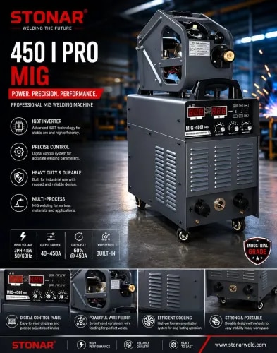
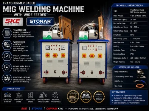
Transformer-Based MIG Welding Machine
A transformer-based MIG (Metal Inert Gas) welding machine is a conventional welding power source that uses a heavy-duty transformer to convert the input AC voltage into a suitable low-voltage, high-current output for MIG welding.
Working principle
The basic power flow is:
AC Input → Transformer → Rectifier → Choke/Inductor → Welding Torch → Workpiece
Transformer: Steps down the high input voltage and increases the available welding current.
Rectifier: Converts the transformer’s AC output into DC, which is generally used for MIG welding.
Choke/Inductor: Smooths the welding current and helps provide a stable arc.
Wire feeder: Continuously feeds the welding wire through the MIG torch.
Gas supply: Provides shielding gas such as CO₂ or an argon/CO₂ mixture to protect the molten weld pool from atmospheric contamination.
Welding torch: Carries the electrode wire, shielding gas, and welding current to the workpiece.
Work clamp: Completes the electrical circuit through the workpiece.
Main components
Input transformer
Bridge rectifier
Inductor/choke
Wire-feed motor and control circuit
MIG welding torch
Shielding-gas regulator and solenoid valve
Welding-current/voltage control
Cooling fan
Work return cable and clamp
Advantages
Simple and robust construction
Relatively easy to repair
Good durability for workshop/industrial use
Suitable for continuous welding
Generally less sensitive to electronic failures than inverter machines
Disadvantages
Large and heavy
Higher power consumption
Less portable
Lower efficiency than modern inverter MIG machines
Transformer and rectifier generate significant heat
In short: A transformer-based MIG welder produces welding power using a conventional transformer and rectifier, while a wire feeder continuously supplies consumable wire and shielding gas protects the weld.
MOTORISED PIPE BANDING MACHINE DISCRIEB
Motorised Pipe Banding Machine
A motorised pipe banding machine is a mechanical machine used to bend or form metal pipes/tubes into circular or curved shapes using a motor-driven mechanism. It is commonly used for fabrication of pipe rings, hoops, frames, and curved pipe components.
Working principle
The basic operation is:
Electric Motor → Gearbox/Reduction Drive → Rollers → Pipe → Curved/Bent Pipe
An electric motor provides the driving power.
A gearbox reduces the motor speed and increases the torque.
The motor drives one or more forming/bending rollers.
The pipe is positioned between the rollers.
As the rollers rotate, they pull the pipe through and gradually bend it.
The roller position is adjusted to control the required bending radius.
Repeated feeding through the rollers produces the desired circular or curved shape.
Main components
Electric motor – Provides mechanical power.
Gearbox – Reduces speed and increases torque.
Drive rollers – Rotate the pipe during forming.
Adjustable roller – Controls the bending radius.
Machine frame – Supports the complete mechanism.
Pipe guide/support – Keeps the pipe correctly aligned.
Control panel – Provides start/stop and motor-control functions.
Emergency stop – Stops the machine quickly during an unsafe condition.
Bearings and shafts – Support and transmit rotary motion.
Advantages
Reduces manual effort
Provides more uniform pipe bending
Faster than manual bending
Suitable for repetitive production
Bending radius can be adjusted
Improves productivity and consistency
Applications
A motorised pipe banding/bending machine can be used for:
Metal pipe fabrication
Furniture and frame manufacturing
Automobile components
Handrails and safety guards
Construction and structural fabrication
Industrial pipe assemblies
In simple terms: A motorised pipe banding machine uses an electric motor and roller mechanism to continuously feed and bend a pipe into a required circular or curved shape.
You said:
20 MM PILLAR DRILL MACHINE SKE DISCRIBE
ChatGPT said:
20 mm Pillar Drill Machine
A 20 mm pillar drill machine is a stationary drilling machine designed to drill holes of up to approximately 20 mm diameter in metal, wood, plastic, and other materials. It consists of a vertical column, motor, spindle, chuck, and adjustable work table.
Working Principle
The basic power transmission is:
Electric Motor → Belt/Pulley Drive → Spindle → Drill Chuck → Drill Bit → Workpiece
The electric motor rotates the spindle through a belt and pulley arrangement.
The drill chuck holds the drill bit securely.
The workpiece is placed and clamped on the drill table.
The operator lowers the spindle using the feed handle.
The rotating drill bit cuts into the workpiece and produces the required hole.
Different spindle speeds can be selected according to the material and drill-bit diameter.
Main Components
Electric motor – Provides rotary power.
Pulley and belt system – Transmits power and allows speed selection.
Spindle – Rotates the drill chuck.
Drill chuck – Holds the drill bit.
Drill bit – Performs the cutting operation.
Feed handle – Moves the drill spindle vertically.
Work table – Supports the workpiece and can usually be adjusted in height/angle.
Pillar/column – Provides vertical support and rigidity.
Base – Supports the complete machine.
Depth stop – Controls the drilling depth.
ON/OFF switch – Controls machine operation.
Specifications
Typical specifications for a 20 mm pillar drill may include:
Maximum drilling capacity: 20 mm
Power: Depending on the machine model
Spindle: Vertical spindle arrangement
Speed: Multiple selectable speeds
Drive: Motor-driven belt and pulley
Operation: Manual feed
Work table: Adjustable
Advantages
Accurate and straight drilling
Better stability than a hand drill
Suitable for repetitive drilling
Adjustable drilling speed
Adjustable drilling depth
Suitable for workshop and fabrication work
Applications
It is commonly used for:
Metal fabrication
Machine workshops
Maintenance work
Engineering workshops
Automobile repair
Drilling holes for bolts, screws, shafts, and fittings
In simple terms: A 20 mm pillar drill machine is a fixed vertical drilling machine in which a motor rotates the drill bit while the operator feeds the bit downward into a securely supported workpiece.
You said:
RILON 205 SYN GASLESS MIG WELDING MACHINE DISCRIEB
ChatGPT said:
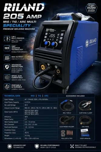
RILON 205 SYN Gasless MIG Welding Machine
RILON 205 SYN is a compact MIG/MMA welding machine designed for welding applications using gasless flux-cored wire and, depending on the exact model/configuration, conventional MIG welding with shielding gas.
Working Principle
The basic welding process is:
AC Input → Inverter Power Supply → Welding Output → Wire Feeder → Welding Torch → Workpiece
The machine converts the incoming electrical supply into controlled welding power using an inverter-based power circuit.
A wire feeder continuously pushes flux-cored welding wire through the MIG torch.
When the wire contacts the workpiece, an electric arc is established.
The arc melts the wire and base metal to form the weld.
With gasless wire, flux inside the wire produces shielding gases and slag, so an external shielding-gas cylinder is generally not required.
The SYN (synergic) control automatically coordinates welding parameters based on selected settings, making operation easier for the user.
Main Components
Inverter power unit – Produces controlled welding current.
Wire-feed mechanism – Continuously feeds welding wire.
MIG torch – Carries the welding wire and current to the workpiece.
Earth/return cable and clamp – Completes the welding circuit.
Control panel – Used to select and adjust welding parameters.
Cooling fan – Helps remove heat from the machine.
Internal control electronics – Provides protection and regulates the welding process.
Wire spool holder – Holds the welding-wire spool.
Gasless MIG Operation
For gasless MIG welding, flux-cored wire is used instead of solid MIG wire. The flux in the wire provides shielding during welding. This makes the machine particularly useful for outdoor fabrication where using a shielding-gas cylinder can be inconvenient.
Advantages
No external shielding-gas cylinder required for gasless welding
Easy and relatively fast welding
Continuous wire feeding increases productivity
Synergic control simplifies parameter setting
Suitable for repair and fabrication work
More portable than conventional transformer-type MIG machines
Can generally be used for multiple welding processes depending on the specific model
Applications
The machine can be used for:
Mild-steel fabrication
Repair and maintenance
Gates and grills
Frames and structures
Automobile repair
General workshop fabrication
Outdoor welding and maintenance
In simple terms: The RILON 205 SYN is a compact inverter welding machine that feeds welding wire automatically. In gasless MIG mode, flux-cored wire produces its own shielding, allowing welding without a separate gas cylinder. The synergic function helps coordinate the welding settings for easier operation.
You said:
GB LASER WELDING MACHINE DISCRIBE
ChatGPT said:
GB Laser Welding Machine
A GB laser welding machine is an industrial welding system that uses a high-power laser beam to join metal components. The concentrated laser energy produces a small, precise molten area, allowing fast welding with relatively low heat input and limited distortion.
Working Principle
The basic process is:
Electrical Power → Laser Source → Optical Fiber → Welding Head → Laser Beam → Workpiece
The laser source generates a high-energy laser beam.
The beam is transmitted to the welding head through an optical fiber.
The welding head focuses the laser beam onto the joint between two metal parts.
The concentrated energy melts the metal at the joint.
As the welding head moves along the joint, the molten metal solidifies and forms a strong weld.
Depending on the material and application, shielding gas such as argon or nitrogen may be used to protect the weld area from oxidation.
Main Components
Laser source – Generates the welding laser.
Laser welding head – Focuses and directs the laser beam.
Optical fiber – Transmits the laser energy from the source to the welding head.
Control system – Controls laser power, welding speed, and other parameters.
Cooling/chiller system – Maintains the laser source and other components at a suitable temperature.
Shielding-gas system – Supplies protective gas when required.
Work table/fixture – Holds the components in the correct position.
Safety enclosure or protection system – Helps protect the operator from laser radiation.
Advantages
High welding speed
Precise and concentrated heat input
Small heat-affected zone
Low distortion compared with many conventional welding processes
Good appearance and consistent weld quality
Suitable for thin and precision metal components
Can reduce post-welding finishing work
Applications
Laser welding machines are commonly used for:
Stainless-steel fabrication
Mild-steel components
Aluminium parts
Sheet-metal fabrication
Automotive components
Electrical and electronic components
Machinery and industrial equipment
Precision fabrication and repair work
In Simple Terms
A GB laser welding machine uses a focused laser beam instead of a conventional welding electrode to melt and join metal parts. Because the laser concentrates heat into a very small area, it can provide fast, accurate welding with low distortion and a clean finish.
You said:
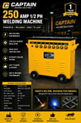
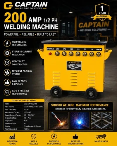
250 AMP 1/2 PHASE STUD TYPE WELDING MACHINE DISCRIBE
ChatGPT said:
250 Amp 1/2 Phase Stud Welding Machine
A 250 Amp stud welding machine is an electrical welding machine used to attach metal studs, pins, bolts, or threaded fasteners directly to a metal surface. The term 1/2 phase may refer to the specific electrical configuration of the machine; the exact input specification should be confirmed from its nameplate.
Working Principle
The basic process is:
AC Input → Welding Transformer/Power Unit → Welding Gun → Stud → Workpiece
The machine supplies a controlled high welding current to the stud.
The stud is placed against the prepared surface of the workpiece.
When the welding gun is activated, an electric arc is produced between the stud and the workpiece.
The arc rapidly melts a small area of the stud and base metal.
The stud is pressed into the molten area.
The current stops and the molten metal solidifies, permanently joining the stud to the workpiece.
Main Components
Welding power unit/transformer – Supplies the required welding current.
Stud welding gun – Holds and positions the stud.
Welding cable – Carries welding current to the gun.
Earth/return cable and clamp – Completes the welding circuit.
Stud holder/collet – Holds different sizes of studs.
Control panel – Controls welding parameters.
Workpiece fixture – Supports the component during welding.
Cooling system/fan – Helps prevent overheating during operation.
Advantages
Very fast stud attachment
No need to drill holes for many applications
Strong and permanent connection
Suitable for repetitive production work
Minimal distortion when correctly adjusted
Clean appearance on the opposite side of the sheet
Useful for attaching threaded studs and fasteners
Applications
It is commonly used for:
Sheet-metal fabrication
Electrical panels and enclosures
Automotive components
Industrial machinery
Boilers and tanks
HVAC ducting
Structural fabrication
Mounting threaded studs and pins
Important Safety Points
Wear a suitable welding helmet, gloves, and protective clothing.
Ensure the workpiece is properly grounded.
Use the correct stud size and welding parameters.
Keep combustible materials away from the welding area.
Inspect cables, gun, and connections before operation.
In simple terms: A 250 Amp stud welding machine uses a controlled electric arc to quickly weld a metal stud directly onto a metal surface, providing a strong fastening point without conventional drilling or threading.
You said:
CONCRET NEEDAL VIBRATOR MACHINE DISCRIBE
ChatGPT said:
Concrete Needle Vibrator Machine
A concrete needle vibrator machine is a construction machine used to compact freshly poured concrete by removing trapped air bubbles and ensuring that concrete properly fills the gaps around reinforcement bars and inside formwork.
Working Principle
The basic process is:
Electric Motor → Flexible Shaft → Vibrating Needle → Fresh Concrete
The motor provides rotary power.
The power is transmitted through a flexible shaft to the vibrating needle.
An eccentric weight inside the needle rotates at high speed and produces vibration.
The vibrating needle is inserted into freshly poured concrete.
The vibration reduces trapped air and allows the concrete particles to settle closely together.
After sufficient compaction, the needle is slowly removed and the process is repeated at another location.
Main Components
Electric motor – Provides the driving power.
Flexible shaft – Transmits rotation from the motor to the vibrator head.
Vibrating needle/head – Produces high-frequency vibration.
Needle casing – Protects the internal vibrating mechanism.
Handle/frame – Allows the operator to carry and control the machine.
Power cable and switch – Supplies and controls electrical power.
Advantages
Removes air pockets from concrete
Improves concrete compaction
Produces denser and stronger concrete
Helps concrete flow around reinforcement
Reduces honeycombing and voids
Improves the surface finish of concrete
Saves time compared with manual compaction
Applications
Concrete needle vibrators are commonly used for:
RCC columns
Beams
Slabs
Foundations
Footings
Walls
Concrete roads
Precast concrete components
Other reinforced-concrete structures
Important Operating Point
The needle should be inserted vertically and gradually into the fresh concrete and moved between nearby points to achieve uniform compaction. Avoid prolonged vibration at one location, as excessive vibration can cause segregation of the concrete.
In simple terms: A concrete needle vibrator uses a rapidly vibrating metal needle inserted into fresh concrete to remove trapped air and compact the concrete, resulting in a stronger and more uniform structure.
You said:
300 Amp 1/2 Phase Stud Welding Machine DISCRIBE
ChatGPT said:
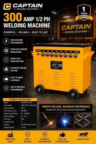
300 Amp 1/2 Phase Stud Welding Machine
A 300 Amp stud welding machine is an electrical welding machine used to weld metal studs, pins, bolts, and threaded fasteners directly onto a metal surface. It is commonly used in fabrication, construction, automobile, and industrial applications.
Working Principle
The basic process is:
Electrical Supply → Welding Power Unit → Welding Gun → Stud → Workpiece
The machine supplies a controlled welding current of up to 300 A.
The stud is placed against the prepared surface of the workpiece.
When the welding gun is triggered, an electric arc is generated between the stud and the workpiece.
The arc melts a small portion of the stud and base metal.
The stud is then brought into the molten metal.
When the current stops, the molten metal solidifies and creates a strong permanent joint.
Main Components
Welding power unit/transformer – Provides the required welding current.
Stud welding gun – Holds and positions the stud.
Stud holder/collet – Holds the required stud size.
Welding cables – Carry current between the machine, gun, and workpiece.
Earth/return clamp – Completes the welding circuit.
Control panel – Used to control welding parameters.
Cooling fan/system – Helps prevent overheating during operation.
Workpiece/earth connection – Provides the electrical return path.
Advantages
Fast stud welding operation
Strong and reliable connection
No drilling or tapping required for many applications
Low distortion of the base material
Suitable for repetitive production work
Easy attachment of threaded studs and pins
Saves fabrication time
Applications
It can be used for:
Sheet-metal fabrication
Electrical panels and enclosures
Automotive components
Machinery manufacturing
Structural fabrication
Boilers and tanks
HVAC equipment
Industrial equipment
Mounting threaded studs and fasteners
Safety Precautions
Use a proper welding helmet/eye protection, gloves, and protective clothing.
Ensure the workpiece is properly connected to the return/earth clamp.
Check welding cables and connections before use.
Use the correct stud, current, and welding time.
Keep flammable materials away from the welding area.
In simple terms: A 300 Amp stud welding machine uses an electric arc to rapidly melt and join a metal stud directly onto a metal surface, creating a strong permanent fastening point without conventional drilling or threading.
You said:
400 Amp 1/2 Phase Stud Welding Machine DISCRIBE
ChatGPT said:
400 Amp 1/2 Phase Stud Welding Machine
A 400 Amp stud welding machine is a heavy-duty welding machine used to weld metal studs, pins, bolts, and threaded fasteners directly onto a metal surface. It is suitable for industrial fabrication, construction, machinery, automotive, and other heavy-duty applications.
Working Principle
The basic operation is:
Electrical Supply → Welding Power Unit → Welding Gun → Stud → Workpiece
The machine supplies controlled welding current, with a maximum rating of approximately 400 A.
The stud is inserted into the stud welding gun and positioned against the workpiece.
When the gun is activated, an electric arc is generated between the stud and the workpiece.
The arc melts the end of the stud and a small area of the base metal.
The stud is then pressed into the molten metal.
When the welding current stops, the molten metal rapidly solidifies and forms a strong permanent joint.
Main Components
Welding power unit/transformer – Supplies high welding current.
Stud welding gun – Holds and positions the stud.
Stud holder/collet – Secures the required stud size.
Welding cables – Carry welding current.
Earth/return clamp – Completes the electrical circuit.
Control panel – Controls welding current and welding time.
Cooling fan/system – Prevents excessive heating of the machine.
Workpiece connection – Provides the return path for welding current.
Advantages
High welding current for heavy-duty applications
Fast stud attachment
Strong and reliable welded joint
No drilling or tapping required in many applications
Low heat input to the surrounding material
Minimal distortion when properly operated
Suitable for repetitive and production welding
Can improve fabrication productivity
Applications
A 400 Amp stud welding machine can be used for:
Heavy sheet-metal fabrication
Structural steel work
Industrial machinery
Boilers and pressure-related fabrication
Storage tanks
Automotive and engineering components
Electrical panels and enclosures
HVAC and ducting work
Construction and infrastructure projects
Safety Precautions
Wear appropriate eye/face protection, welding gloves, and protective clothing.
Ensure proper workpiece grounding/return connection.
Inspect the welding gun, cables, and connectors before operation.
Use the correct stud diameter and welding parameters.
Keep combustible materials away from the welding area.
Provide adequate ventilation and follow the machine manufacturer's instructions.
In simple terms: A 400 Amp stud welding machine uses a controlled electric arc and high welding current to quickly and securely weld studs or threaded fasteners directly onto metal surfaces, making it suitable for heavy-duty industrial fabrication.
You said:
1''(25MM) SKE PILLAR DRILL MACHINE DISCRIBE
ChatGPT said:
1“ (25 mm) SKE Pillar Drill Machine
A 1” (25 mm) SKE Pillar Drill Machine is a stationary drilling machine designed for drilling holes of up to approximately 25 mm diameter in metal, wood, and other suitable materials. It is commonly used in fabrication, engineering, repair, and workshop applications.
Working Principle
The basic power transmission is:
Electric Motor → Belt & Pulley → Spindle → Drill Chuck → Drill Bit → Workpiece
The electric motor provides rotary power.
The belt and pulley system transfers power from the motor to the spindle.
The drill chuck securely holds the drill bit.
The workpiece is placed and firmly clamped on the drill table.
The operator lowers the spindle using the feed handle.
The rotating drill bit cuts into the workpiece and produces the required hole.
Different spindle speeds can be selected according to the material and drill-bit size.
Main Components
Electric motor – Provides power for drilling.
Pulley and belt drive – Transmits power and provides different spindle speeds.
Spindle – Rotates the drill chuck.
Drill chuck – Holds the drill bit.
Drill bit – Performs the cutting operation.
Feed handle – Moves the spindle up and down.
Adjustable work table – Supports the workpiece and can be positioned at the required height.
Pillar/column – Provides rigid vertical support.
Base – Supports the entire machine.
Depth stop – Helps maintain a consistent drilling depth.
ON/OFF switch – Controls machine operation.
Advantages
Maximum drilling capacity of approximately 25 mm (1 inch)
Accurate and straight drilling
Strong and rigid construction
Suitable for repetitive drilling
Multiple spindle-speed selection
Adjustable drilling depth
Better control than a handheld drill
Suitable for workshop and fabrication work
Applications
The machine is commonly used for:
Metal fabrication
Engineering workshops
Machine shops
Automobile repair and maintenance
Structural fabrication
Drilling holes for bolts, shafts, fasteners, and fittings
General maintenance work
Safety Precautions
Clamp the workpiece securely before drilling.
Wear appropriate eye protection.
Do not hold small workpieces by hand while drilling.
Select the correct spindle speed and drill bit for the material.
Keep loose clothing and hands away from rotating parts.
Switch off and isolate the machine before changing the drill bit.
In simple terms: A 1' (25 mm) SKE Pillar Drill Machine is a heavy-duty stationary drill that uses a motor-driven spindle and drill bit to make accurate holes up to about 25 mm diameter in various materials.
You said:
13MM DRILL PILLAR DRILL MACHINE DISCRIBE
ChatGPT said:
13 mm Pillar Drill Machine
A 13 mm pillar drill machine is a compact, stationary drilling machine designed to drill holes up to approximately 13 mm in diameter in materials such as mild steel, aluminium, wood, and plastic. It is commonly used in workshops, fabrication units, maintenance, and engineering work.
Working Principle
The basic operation is:
Electric Motor → Belt & Pulley → Spindle → Drill Chuck → Drill Bit → Workpiece
The electric motor provides rotary power.
The belt and pulley system transfers power to the spindle.
The drill chuck holds the drill bit securely.
The workpiece is placed on the drill table and securely clamped.
The operator lowers the rotating drill bit using the feed handle.
The drill bit cuts the material and produces the required hole.
Spindle speed can be adjusted according to the material and drill-bit size.
Main Components
Electric motor – Provides drilling power.
Pulley and belt system – Transfers power and allows speed adjustment.
Spindle – Rotates the drill chuck.
Drill chuck – Holds the drill bit.
Drill bit – Performs the drilling operation.
Feed handle – Controls vertical movement of the spindle.
Work table – Supports the workpiece.
Pillar/column – Provides rigid vertical support.
Base – Supports the complete machine.
Depth stop – Controls the required drilling depth.
ON/OFF switch – Controls machine operation.
Advantages
Drilling capacity up to approximately 13 mm
More accurate than a handheld drill
Stable and rigid construction
Suitable for repetitive drilling
Adjustable spindle speed
Easy drilling-depth control
Suitable for small and medium workshop jobs
Applications
A 13 mm pillar drill is commonly used for:
General workshop work
Light metal fabrication
Machine maintenance
Automobile repair
Electrical panel fabrication
Furniture and hardware work
Drilling holes for bolts, screws, and fasteners
Safety Precautions
Securely clamp the workpiece before drilling.
Wear suitable safety goggles.
Never hold small workpieces by hand while drilling.
Keep hands and loose clothing away from rotating parts.
Select the correct drill speed for the material.
Switch off the machine before changing the drill bit.
In simple terms: A 13 mm pillar drill machine is a fixed vertical drilling machine that uses a motor-driven spindle to make accurate holes up to about 13 mm diameter in suitable materials.
You said:
RILON MIG 160 E WELDING MACHINE DISCRIBE
ChatGPT said:
RILON MIG 160E Welding Machine
The RILON MIG 160E is a compact IGBT inverter welding machine designed for MIG, gasless MIG, and MMA/ARC welding. It is a portable machine suitable for fabrication, maintenance, repair, and workshop applications. The RILON product information lists a 220 V single-phase input and a MIG output range of 30–160 A.
G
gbkore.com
+1
Working Principle
The basic operation is:
220 V AC Input → IGBT Inverter → DC Welding Output → Wire Feeder → MIG Torch → Workpiece
The IGBT inverter circuit converts the incoming electrical power into controlled welding power.
The internal wire feeder continuously feeds welding wire through the MIG torch.
When the wire contacts the workpiece, an electric arc is created.
The arc melts the welding wire and the base metal to form the weld joint.
In gasless MIG mode, flux-cored wire provides the shielding required for welding, so an external gas cylinder is not normally required.
The machine also supports MMA/ARC welding.
G
gbkore.com
Main Components
IGBT inverter power unit – Produces controlled welding current.
Wire feeder – Feeds welding wire continuously.
MIG welding torch – Carries the wire and welding current to the workpiece.
Earth clamp and cable – Completes the welding circuit.
Control panel/LCD display – Used to set and monitor welding parameters.
Wire spool holder – Holds the welding wire.
Cooling fan – Helps maintain the machine temperature.
Protection circuit – Provides protection against conditions such as overheating and over-current.
G
gbkore.com
+1
Typical Specifications
Specification RILON MIG 160E
Input 220 V, 1 Phase, 50–60 Hz
MIG Output 30–160 A
MMA Output 20–140 A
MIG Rated Output 160 A / 22 V / 25% duty cycle
No-load voltage 60 V
Technology IGBT Inverter
Dimensions Approx. 428 × 211 × 338 mm
Weight Approx. 7 kg
These specifications are from RILON product information; exact specifications can vary by regional/model version.
G
gbkore.com
Advantages
Compact and portable design
MIG and gasless MIG capability
MMA/ARC welding capability
Smooth and stable arc
Low spatter
Easy parameter adjustment
Suitable for outdoor gasless welding
Built-in protection against overheating and electrical faults
Suitable for fabrication and maintenance work
G
gbkore.com
+1
Applications
The RILON MIG 160E can be used for:
Mild-steel fabrication
Gates and grills
Sheet-metal work
Automobile repair
Machinery maintenance
General workshop fabrication
Repair and field welding
Small structural and fabrication jobs
In simple terms: The RILON MIG 160E is a lightweight 160 Amp inverter MIG welder that automatically feeds welding wire and creates an electric arc to join metal. Its gasless MIG function makes it particularly convenient where carrying a shielding-gas cylinder is difficult.
G
gbkore.com
G
Sources
You said:
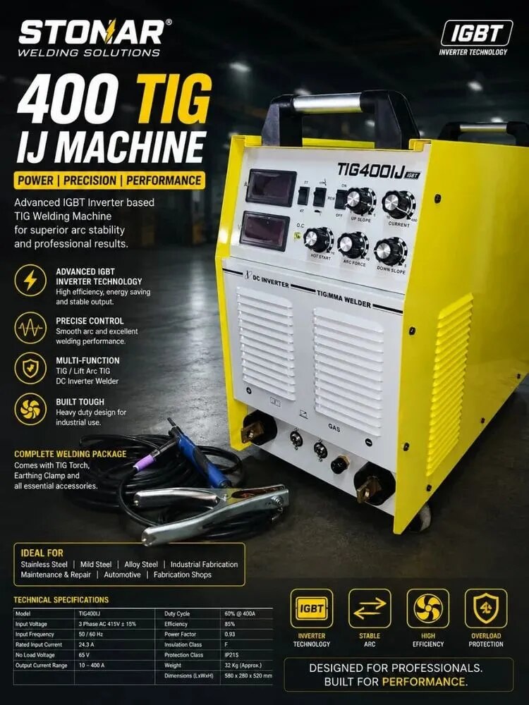
TIG 400 ARC WELDING MACHINE DISCRIBE
ChatGPT said:
TIG 400 ARC Welding Machine
A TIG 400 ARC Welding Machine is a heavy-duty industrial welding machine used for TIG (Tungsten Inert Gas) welding and MMA/ARC welding. Typical TIG 400 models provide up to 400 A welding current and are commonly designed for 3-phase 415 V power supply, although specifications vary by manufacturer.
S
Starblaze India
+1
Working Principle
The basic operation is:
3-Phase AC Supply → IGBT Inverter → Welding Current → TIG Torch/Electrode → Workpiece
The IGBT inverter converts the input electrical power into controlled welding current.
In TIG mode, a non-consumable tungsten electrode produces the welding arc.
Argon or another suitable shielding gas protects the molten weld pool from atmospheric contamination.
A separate filler rod can be added when required.
In ARC/MMA mode, a consumable coated electrode is used to create the welding arc.
The machine controls the welding current to provide stable and consistent welding performance.
Many TIG 400 models include features such as HF arc ignition, 2T/4T operation, adjustable up/down slope, arc force, and gas pre/post-flow.
S
Starblaze India
+1
Main Components
IGBT inverter power unit – Produces controlled welding output.
TIG welding torch – Holds the tungsten electrode and supplies shielding gas.
Tungsten electrode – Produces the TIG welding arc.
Gas supply system – Supplies shielding gas such as argon.
Earth/return cable and clamp – Completes the welding circuit.
Control panel – Used to adjust welding current and other parameters.
Cooling fan or water-cooling system – Controls operating temperature.
ARC electrode holder – Used for MMA/ARC welding.
Digital display – Shows welding-current settings on many models.